
Wednesday, October 31, 2012
THIS BLOG DISCONTINUED
Whisper X build info from here onwards now resides in a dropbox folder. Once you receive your kit I'll provide the link to the folder.
Tuesday, October 18, 2011
Elevator bellcrank

More details available at http://whisperaircraft.blogspot.com/2009/03/horizontal-stab-fairings.html
Tailplane installation


Aileron pushrod holes through fuselage side

Monday, June 27, 2011
Elevator pulley bracket

Thursday, June 23, 2011
Fin ribs
Roughen bond areas thoroughly and apply cotton flox.
Hold ribs during bonding using 4mm pop rivets.
![]() Ensure that rib faces are perpendicular to the split line mark on the front fin spar. Ensure also that the ribs are exactly parallel to each other or slightly further apart at their front points. This will allow for easy fitment of the horizontal stab later.
Ensure that rib faces are perpendicular to the split line mark on the front fin spar. Ensure also that the ribs are exactly parallel to each other or slightly further apart at their front points. This will allow for easy fitment of the horizontal stab later.
Hold ribs during bonding using 4mm pop rivets.

Tuesday, June 21, 2011
Fin skin (right hand side)

Monday, June 20, 2011
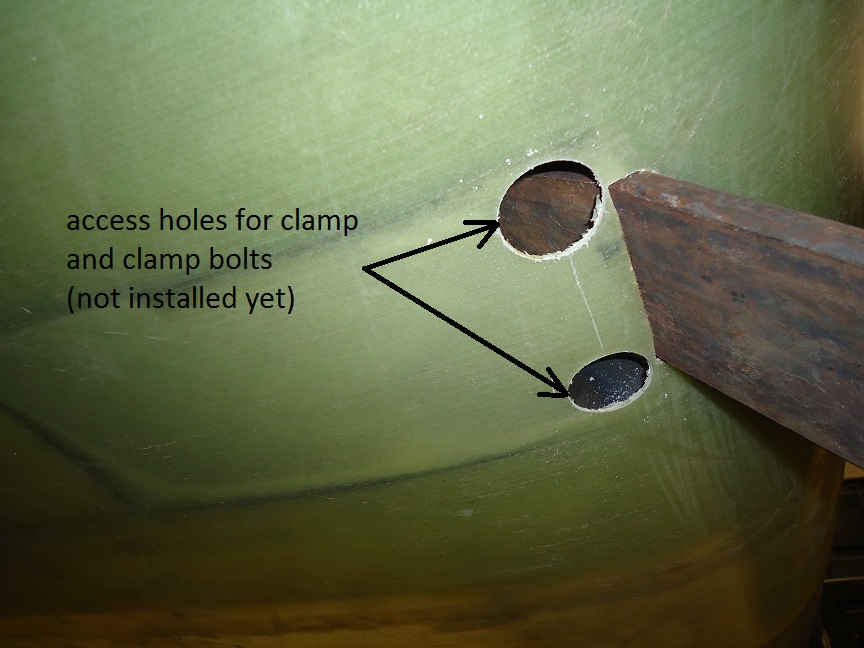
Fin Spars
Once absolutely sure that both spars are vertical drill 4 holes to attach the front spar to its bulkhead. The 4 holes will ultimately be used for the M5 / 3/16" "chicken bolts" which you'll use during bonding. Drill the rear spar for 4mm pop rivets to be used during bonding. Disassemble everything, roughen bond areas, apply cotton flox and re assemble just the spars. Install the "chicken bolts" to hold the front spar and the pop rivets to hold the rear spar. Once cured drill out the pop rivets. Remove the chicken bolts (or if a chicken like me - leave them in!). Roughen and apply layers of 280gsm around the spars, pulley mount area and tailspring clamp attach area as shown.


Wednesday, June 8, 2011
Cockpit edge longerons


Monday, June 6, 2011
Undercarriage - main bolt
Level the aircraft (a self levelling laser is very useful for this)
Insert the two undercarriage legs as far as they will go into the steel housings (the curved edge faces forwards)
Retract them 5 mm (for clearance)
Determine and mark the position of the top hole. Confirm that both marks are at the same height (the laser is useful for this). This measurement will ensure that your aircraft will stand straight and not have one wing lower than the other!
The hole position is midway between the undercarriage bulkheads (fore/aft measurement)
Drill 3/8"
Fabricate suitable mild steel load spreaders as shown. Suggested material is 50 by 50 by 5mm mild steel angle cut down to 25mm width and shaped as shown. Radius the outer edges to snugly fit the corner fillet.


 Temporarily bolt the legs on.
Also shown is a dolley to assist in moving the fuselage around.
Insert the two undercarriage legs as far as they will go into the steel housings (the curved edge faces forwards)
Retract them 5 mm (for clearance)
Determine and mark the position of the top hole. Confirm that both marks are at the same height (the laser is useful for this). This measurement will ensure that your aircraft will stand straight and not have one wing lower than the other!
The hole position is midway between the undercarriage bulkheads (fore/aft measurement)
Drill 3/8"
Fabricate suitable mild steel load spreaders as shown. Suggested material is 50 by 50 by 5mm mild steel angle cut down to 25mm width and shaped as shown. Radius the outer edges to snugly fit the corner fillet.


Also shown is a dolley to assist in moving the fuselage around.
Wednesday, June 1, 2011
Undercarriage bulkheads - phase 3


280gsm (500mm wide) strips at 45deg 6 off (full roll width)
500gsm UD 150mm wide 1700mm long 4 off
280gsm at 45 deg (200mm by 300mm) 20off
Note: 410gsm (same total mass) can be substituted for the 280gsm but it is slightly more difficult to drape into such a deep trough.
Sand thoroughly.
Apply cotton flox in the sharp corners and into the holes in the steel
Start with a 280gsm and alternate with the UD (The UD lies in the bottom of the trough only whereas the 280gsm goes up the sides as well.
Add 10 pieces of 280gsm (200 by 300mm) each side as indicated in red in the pic above
Finish with peel ply
Monday, May 30, 2011
Undercarriage bulkheads - phase 2


Sunday, May 29, 2011
Top engine mount points


Remove peel ply as required and sand thoroughly.
Cutting list for both top mounts (share between left and right)
410gsm (140mm wide) 1300mm long (roll width) 20 pieces
500gsm UD (125mm wide) 1000mm long 20 pieces
500gsm UD (125mm wide) 1200mm long 10 pieces
Start with a piece of 410 going 100mm up onto the firewall and as far back as its 1300mm length extends. There is a kink near the front edge of the canopy which the 410 can go around.
Next is a piece of UD (1000mm long) going 100mm up the firewall and straight back onto the fuselage side as shown in the pics. UD cannot be kinked.
Third is a piece of 500gsm (1200mm long) overlapping the other UD and extending back to about 150mm past the aft edge of the canopy sill as per the pic.
Avoid letting the layers climb onto the underside of the canopy sill as this will clash with the longeron moulding to be attached there later.
Continue in this order. Finish with peel ply. Work slowly ensuring that all bubbles are removed - this is a critical part of the structure!!. Also ensure that the glass onto the firewall is centred over the pilot hole. Making a dark circle with a felt tipped pen around the hole helps.
Saturday, May 28, 2011
Undercarriage bulkheads


1) 350 wide 410gsm (5 off)
2) 150 wide 500gsm 1200mm long (6off) - one piece on vertical face, one piece on fuselage
3) 100 wide 410gsm 1200mm long (4off)
alternate 1) and 2) and finish with 3)
Peel ply whole area
Monday, May 23, 2011
Undercarriage humps - tacking in place


Sunday, May 22, 2011
Lower engine mount strengthening layers
Cut 10 strips 1100mm long of 410gsm cloth 140mm wide.
Cut 10 strips 750mm long of 410gsm cloth 140mm wide.
Cut 10 strips 1100mm long of 500gsm UD cloth 140mm wide (UD strips are cut using a sharp blade between the roving bundles).
Cut 10 strips 750mm wide of 500gsm UD cloth 140mm wide
Above cutting list is enough for both lower engine mount points (share between left and right)
Mix about 300g of resin at a time or a bit less if weather is warm (to avoid exotherm) and using a brush and squeegee laminate as follows:
All layers go up onto the firewall plywood by 100mm.
Start with the long strips first.
Alternate between UD and 410
Shorter strips last
Finish with a layer of peel ply
Strips pass just outboard of gear cutouts and kink slightly at this point to become parallel to longitudinal axis of aircraft. Squegee out all bubbles and work slowly to avoid any dry spots.
Make sure that the lower fuselage is not deformed at all during curing...support it aft of the area where the strips go.
 All "resin" mentioned in this manual is either Ampreg 22 (mix ratio 100:28) or Ampreg 21 (mix ratio 100:33). Both come with different cure rate hardeners. Typically "extra slow" is used for very thick lay ups such as spar caps and "slow" or "standard" is used elsewhere. "Fast" is only used for small tacking jobs and mixing filler (microballoons).
Cut 10 strips 750mm long of 410gsm cloth 140mm wide.
Cut 10 strips 1100mm long of 500gsm UD cloth 140mm wide (UD strips are cut using a sharp blade between the roving bundles).
Cut 10 strips 750mm wide of 500gsm UD cloth 140mm wide
Above cutting list is enough for both lower engine mount points (share between left and right)
Mix about 300g of resin at a time or a bit less if weather is warm (to avoid exotherm) and using a brush and squeegee laminate as follows:
All layers go up onto the firewall plywood by 100mm.
Start with the long strips first.
Alternate between UD and 410
Shorter strips last
Finish with a layer of peel ply
Strips pass just outboard of gear cutouts and kink slightly at this point to become parallel to longitudinal axis of aircraft. Squegee out all bubbles and work slowly to avoid any dry spots.
Make sure that the lower fuselage is not deformed at all during curing...support it aft of the area where the strips go.

Saturday, May 21, 2011
Engine mount attach strengthening - preparation

Firewall - marking out engine mount attach points

Friday, May 13, 2011
Fitting firewall plywood

Monday, May 9, 2011
Fuselage - preliminary work


Subscribe to:
Posts (Atom)